Fiber optic patch cords are used to make patch cords from the device to the fiber optic cabling link. It has a thicker protective layer and is generally used in the connection between the optical transceiver and the terminal box.
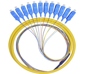
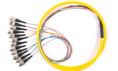
Pigtail is also called pigtail wire, only one end has a connecting head, and the other end is a broken head of an optical cable core, connected to other optical cable cores by welding, often appearing in the optical fiber terminal box, used to connect the optical cable and the optical fiber transceiver (couplers, jumpers, etc. are also used in between).
Optical fiber connector is a detachable (active) connection between the optical fiber and the optical fiber device, it is the two end faces of the optical fiber precision docking, so that the optical energy output by the transmitting optical fiber can be coupled to the receiving optical fiber to the greatest extent, and the impact on the system due to its intervention in the optical link is minimized, which is the basic requirement of the optical fiber connector. To a certain extent, optical fiber connectors also affect the reliability and performance of optical transmission systems.
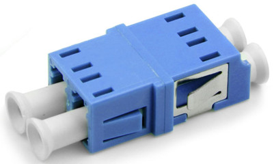
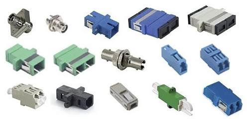
Fiber coupler / flange
1. Introduction to fiber coupler/flange
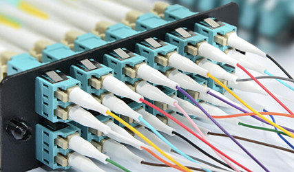
Fiber coupler (Coupler), also known as splitter, connector, adapter, flange, is used to realize optical signal splitting / combining, or for extending the optical fiber link components, belongs to the field of optical passive components, in telecommunications networks, cable TV networks, user loop systems, area networks will be applied.
Fiber couplers can be divided into:
l Standard coupler (waveguide, double-branch, units 1×2, i.e. splitting the optical signal into two powers)
l Direct coupler (connect 2 fibers of the same or different type of fiber interface to extend the fiber link)
l Star/tree coupler
l and wavelength multiplexers (WDM, if the wavelength is high-density separation, that is, the wavelength spacing is narrow, it is DWDM)
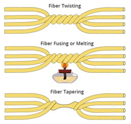
There are three production methods: sintering (Fuse), micro optical (Micro Optics), optical waveguide (Wave Guide), and the sintering method accounts for the majority (about 90%)
The production method of sintering method is to sinter and stretch two optical fibers together, so that the core is aggregated together to achieve optical coupling, and the most important production equipment is the optical fiber splicer, which is also an important step, although the important step part can be manufactured by the machine, but after sintering, it is still necessary to work to detect the package, so the labor cost accounts for about 10~15%, and the use of manual detection packaging must ensure the consistency of quality, which is also necessary to overcome during mass production, but the technical difficulty is not as good as DWDM High modules and optical active components,
2. Classification of fiber couplers
According to the different coupling fibers, there are the following classifications:
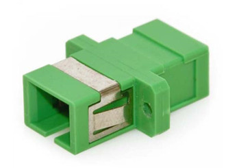
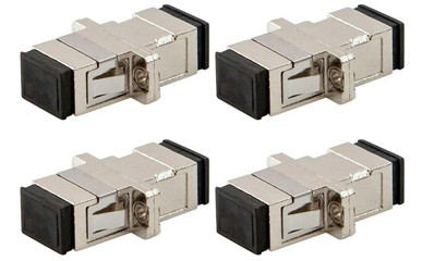
l SC fiber coupler
Applied to SC fiber interface, it looks very similar to RJ-45 interface, but SC interface appears flatter, its obvious difference is still the contacts inside, if it is 8 thin copper contacts, it is RJ-45 interface, if it is a copper pillar is SC fiber interface.
l LC fiber coupler
Applied to LC fiber interface, the connector connecting SFP module, it is made of an easy-to-operate modular jack (RJ) latch mechanism. (commonly used by routers)
l FC fiber coupler
Applied to FC optical fiber interface, the external reinforcement method is to use a metal sleeve, and the fastening method is a screw buckle. It is generally used on the ODF side (the most used on the distribution frame)
l ST fiber couplers
Applied to ST optical fiber interface, commonly used in optical fiber distribution frame, the shell is round, and the fastening method is screw buckle. (For 10Base-F connections, the connector is usually an ST type.) Commonly used in fiber distribution frames)
3. The principle of fiber coupler
Fiber coupler is a device that can be detachable (active) connection between the optical fiber and the optical fiber, which is to precisely connect the two end faces of the optical fiber so that the optical energy output of the transmitting optical fiber can be coupled to the receiving optical fiber to the maximum extent, and make it intervene in the optical link to minimize the impact on the system.
For waveguide fiber couplers, it is generally a component with a Y-shaped branch, and the optical signal input by one optical fiber can be divided in equal parts. When the opening angle of the coupler branch increases, the light leakage into the cladding will increase and increase the excess loss, so the opening angle is generally within 30°, so the length of the waveguide fiber coupler cannot be too short.
4. The role of fiber coupler
The photocoupler is composed of two parts: the emitting light source and the light receiver. The light source and the light receiver are assembled in the same closed housing and isolated from each other by transparent insulators. The pin of the light source is the input end, the pin of the light receiver is the output end, the common light source is the light-emitting diode, the light receiver is a photodiode, a phototransistor and so on.
The function of fiber coupler is to realize optical signal splitting/combining, or components for extending optical fiber links, which belong to the field of optical passive components and are applied to telecommunication networks, cable TV networks, user loop systems, and area networks. The main functions are:
l Converts optical signals into electrical signals
l Couple multimode signals into singlemode signals
l Turn on the cross-sectional fiber holes of the two fiber connectors
l Connect two sets of optical signals to each other
Fiber optic termination box
The optical fiber terminal box is the terminal connector of an optical cable, one end of his is an optical cable, the other end is a pigtail, which is equivalent to splitting an optical cable into a single optical fiber device, installed on the wall of the user's optical cable terminal box,
Its function is to provide fiber-to-fiber splicing, fiber-to-pigtail splicing, and optical connector handover. and provide mechanical protection and environmental protection for optical fibers and their components, and allow appropriate inspections to maintain the highest standards of fiber management.
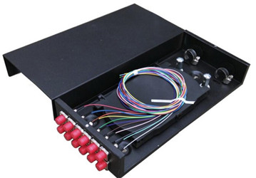
4 ports SC
8 ports SC
8-port FC
8-port ST
8 ports SC
4 ports out of pigtail
12 ports of pigtail
24 pigtails out
24-port pull-out type
24-port fixed type
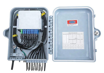
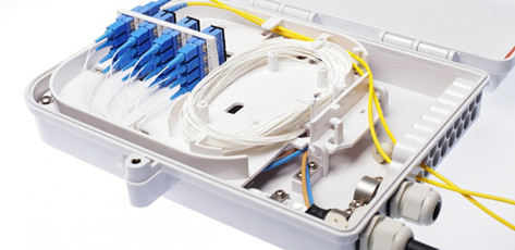
Wall-mounted fiber termination box:
The optical cable terminal box is used for the straight-through connection and divergence connection of indoor optical cable, plays the role of joint protection and pigtail disc storage of optical fiber, with a capacity of 4 to 8 cores, and is suitable for both strip and non-ribbon optical cables.
4. 8-port wall-mounted optical fiber terminal box, model: ST, SC, FC type.
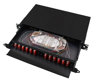
Rackmount fiber termination box:
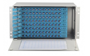
The optical cable terminal box is used for the straight-through connection and divergence connection of indoor optical cable, plays the role of joint protection and pigtail tray storage of optical fiber, with a capacity of 12-48 cores, and is suitable for both strip and non-ribbon optical cables.
12, 24 port rack type optical fiber terminal box, model: ST, SC, FC type.
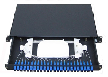
Product Description:
l Equipped with optical cable fixtures, welding plates, and wire loops.
l It has the function of insulating the metal components of the optical cable from the terminal box shell and easily leading out the grounding.
l It can provide sufficient optical cable termination placement and residual optical fiber storage space.
l Special specifications and sizes can be customized according to user needs.
Usage environment:
Ambient temperature: -25°C—140°C;
Relative temperature: ≤85% (at 130°C);
Atmospheric pressure: 70KPa—106KPa;
Insulation resistance:
The insulation resistance between the metal components of the optical cable terminal box and the metal reinforcement core of the optical cable, between the metal components of the optical cable, and between the metal components of the optical cable and the ground is greater than 2×10⁴HΩ. The radius of curvature of optical fiber storage of optical cables is greater than 45mm.
Electrical strength:
Between the metal components of the optical cable terminal box and the metal reinforcement core of the optical cable, between the optical cable and the metal components, and between the metal components of the optical cable and the ground, there is no breakdown under the action of 15KV DC voltage for 1min, and there is no arcing phenomenon.
Optical cable splicing box
First, the introduction of optical cable connection box
The optical cable connection box, also known as the optical cable connector box and barrel, is the place where the end of the optical cable is accessed, and then the optical switch is accessed through the optical fiber jumper.
Prevent the aging of materials caused by heat, cold, light, oxygen and microorganisms in nature, and have excellent mechanical strength, strong optical cable connector box shell and main structural parts can withstand the harshest environmental changes, while playing a flame retardant, waterproof role, so that vibration, impact, optical cable stretching, distortion, etc. are protected.
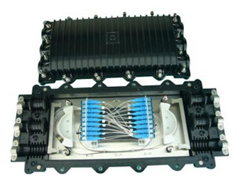
Horizontal
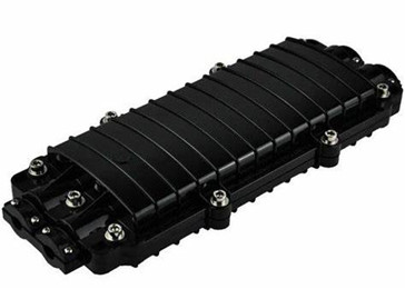
Vertical
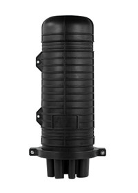
The internal structure of the optical cable splicing box
Horizontal
Vertical
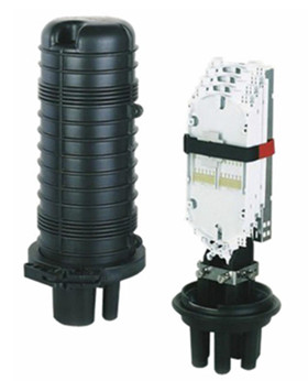
l Support frame: is the main body of internal components.
l Optical cable fixing device: used for fixing optical cable and base and fixing optical cable strengthening components. First, the internal fixing of the optical cable reinforcement core; The second is the fixation of the clamping of the optical cable and the support frame; Third, the optical cable and the connector box inlet and outlet cables are sealed and fixed with heat shrinkable sheaths.
l Optical fiber placement device: can store optical fiber connectors and residual optical fibers in order, the length of the remaining optical fiber should not be less than 1 meter, and the curved diameter of the remaining optical fiber disc is not less than 35mm. Among them, the containment tray can have four layers, the capacity is large, and the containment tray can be adjusted according to the number of cores connected by the optical cable.
l Optical fiber joint protection: the protective sleeve after heat shrinking can also be used on the fiber core fixing clip in the containment tray.
l Sealing of optical cable and connector box: polish the junction of the connector box and the optical cable with an emery cloth at the entrance of the optical cable and the base, wipe the polishing place with detergent, paste aluminum foil, and then put the heat shrinkable tube at the cable of the connector box, and slowly heat the two ends with a blowtorch to make the entire heat shrinkable tube completely shrink
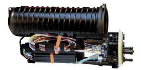
The use, characteristics and classification of optical cable connection box
Use:
l It is suitable for the direct and branch connection of various structural optical cable laying methods such as overhead, pipeline, and direct burial.
l Connection in the terminal room of the structured optical cable.
l Optical cable splicing boxes are usually suitable for indoor or non-open outdoor use, not suitable for open air use, if used, protective measures should be taken. Working temperature: indoor type: -5 °C ~ +40 °C; Outdoor type: -20°C-+60°C.
Peculiarity:
Can play the role of protection and connection, the box body is made of reinforced plastic, high strength, corrosion resistance, mature structure, reliable sealing, convenient construction.
Classify:
l According to the optical cable connection method, it can be divided into straight-through type and divergence type.
l According to the classification of whether the adapter can be assembled, it can be divided into assembleable adapter type and non-assembly adapter type.
l According to the classification of shell materials, it can be divided into plastic shell and metal shell.
4. The use of optical cable splicing box
Fiber preparation
l In addition to the outer skin of the optical cable, (if any, please remove the shielding and armor) and then remove each wrapping layer until the loose tube is exposed, the specific method, please follow the standard method steps recommended by the optical cable manufacturer, and the preparatory length is 3m.
l Clean the loose sleeve and the reinforced core sheath with detergent, remove the excess filling sleeve, and polish the outer skin of the optical cable 150mm long with the sandpaper provided.
Fiber optic cable installation
l Select the sealing ring with the smallest inner diameter according to the outer diameter of the optical cable, and put the two sealing rings on the optical cable.
l Put the optical cable into the corresponding hole.
l Connect shielding and grounding.
l Wrap self-adhesive sealing tape between the two sealing rings, so that the sealing tape is wound to level with the outer diameter of the sealing ring to form an optical cable sealing end.
l Press the sealing end of the optical cable into the hole of the optical cable.
l Use the hose hoop to pass through the optical cable stiffener fixing base and the cable core bracket, fix the optical cable on the base of the connector box, and tighten the throat clamp screw until the throat clamp is tightened.
l Tie-up nylon cable ties on the optical cable and cut the remaining length.
l For the rest of the unused optical cable holes, please seal them with plugs. The plug is also wrapped with sealing tape.
l Wrap the reinforcing member on the countersunk screw of the welding plate support and press it.
Fiber splicing
l Prepare the optical fiber to be coiled 1.5 times after the coil, and then coil all the remaining fibers in the box.
l Please use a single-core buffer tube for single-core optical fiber upper disk, and use a ribbon buffer tube for strip optical fiber upper coil. Tie-up with nylon cable ties at the inlet of the welding plate.
l Connect two (belt) optical fibers according to the prescribed method, the connector is snapped into the card slot of the welding unit, and the remaining length should be coiled in the disk.
l Put the welding plate on the lid and press it into place.
l According to the different capacity required by the connector box, determine the number of plates superimposed on the welding plate, and the superimposed type of the welding plate must meet the snap into the welding unit of the optical fiber connector and check and maintain the requirements.
l Every two superimposed welding plates can catch six holes on the rubber fold and jam the three convex twists on each of the upper and lower disks; Four rubber folds, two symmetrical positions on both sides of the disk, such as superimposing five welding plates, according to the above method, the two-layer disc and the three-layer disc are buckled, the three-layer disc and the four-layer disc are buckled, the four-layer disc and the five-layer disc are buckled, and so on, the five discs are stably superimposed together.
l When it is necessary to inspect or maintain the welding of a certain layer of the disk, as long as the two folds of the upper layer of the single side of the disk are removed, the welding plate can be opened like a turning page.
The box sealed
l Box packaging: tighten the valve nozzle and grounding screw before the box is packaged. Insert the sealing strip into the sealing groove around the box; The "U" groove at both ends of the connector box is also embedded in the groove with sealing strips. Note: Use the sealing strip, do not pull the sealing strip artificially to avoid leakage.
l Gently close the upper cover of the connector box, screw in the fastening bolt, tighten the fastening order in the order of the number indicated on the cover, and use a torque wrench to prevent the tightening, and the torque reaches 25N·m.
l After 5 minutes, tighten the torque wrench sequentially, and the torque still reaches 25N·m.
Removal of the lid
l Loosen the 10 fastening bolts in order, at this time the cover and seat are still together.
l Take four fastening bolts and insert them into the four corners of the box, and screw them symmetrically and evenly into the top cover at the four corners, so that the cover and seat are separated by up to 6mm.
l After 5 minutes, the top cover is evenly separated by > 6mm until the cover and seat can be easily separated by hand. Note: The cover must be gently removed during separation to avoid damage to the spliced fiber.
ODF distribution frame
1. Introduction to optical fiber distribution frame
Optical fiber distribution frame is an important supporting equipment in the optical transmission system, it is mainly used for optical fiber splicing, optical connector installation, optical path adjustment, storage of excess pigtails and protection of optical cable, etc., it plays an important role in the network security operation and flexible use of optical fiber communication.
2. Characteristics of optical fiber distribution frame
In recent years, in the actual work of optical communication construction, through the comparison of the use of several products, we believe that the selection of optical fiber distribution frame should focus on the following aspects
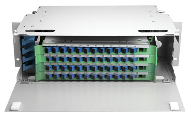
(1) Core capacity
An optical fiber distribution frame should be able to fully put the optical cable with the largest number of cores in the bureau on the shelf, and where possible, several optical cables with more interconnections can be placed on a shelf to facilitate optical path deployment. At the same time, the capacity of the distribution frame should correspond to the general optical cable core number series, so that the waste of optical fiber distribution frame capacity due to improper matching can be reduced or avoided when used.
(2) Functional types
As the terminal equipment of optical cable lines, the optical fiber distribution frame should have four basic functions.
l Fixed functionality
After the optical cable enters the rack, its outer sheath and reinforcement core should be mechanically fixed, ground wire protection parts should be installed, end protection treatment should be carried out, and the optical fiber should be grouped and protected.
l Welding function
After the optical fiber led out of the optical cable is spliced with the tail cable, the excess optical fiber is coiled and stored, and the splice joint is protected.
l Provisioning capabilities
Plug the connector attached to the patch cable to the adapter and realize optical path docking with the optical connector on the other side of the adapter. Adapters and connectors should be able to be plugged in and unplugged flexibly; The optical path can be freely deployed and tested.
l Storage capabilities
Provides storage for various cross-connected optical cables between racks, allowing them to be placed regularly and neatly. There should be appropriate space and methods in the optical fiber distribution frame, so that this part of the optical connection line is clearly routed, easy to adjust, and can meet the requirements of the minimum bending radius
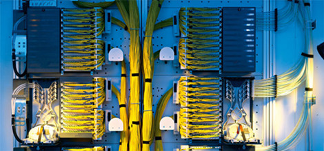
With the development of optical fiber networks, the existing functions of optical fiber distribution frames can no longer meet many new requirements. Some manufacturers directly install some optical fiber network components such as optical splitters, wavelength division multiplexers and optical switches directly to the optical fiber distribution frame. This not only makes these components easily applied to the network, but also adds functionality and flexibility to the fiber distribution frame.
The number of common ODF distribution frame cores is:
12 cores
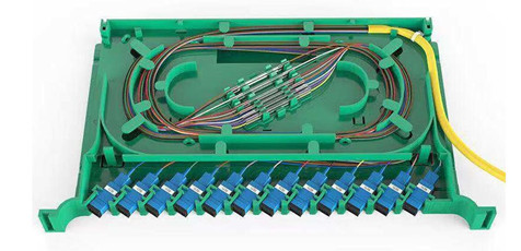
24 cores
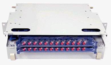
48 cores
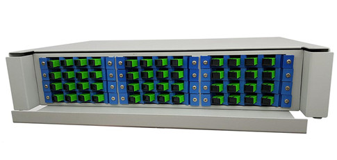
72 cores
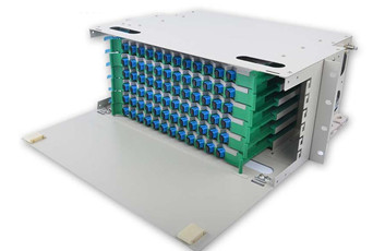
96 ores
